Mastering Input Filter Design: Achieving EMC Compliance for Power Converters
- Dario Fresu

- Apr 3
- 4 min read
Designing switching power converters is not just about achieving efficient voltage regulation; it involves navigating the complex landscape of electromagnetic compatibility (EMC). Among the critical components in this endeavor is the input filter. This article explores the strategic role of input filters, their influence on closed-loop dynamics, and the tools required to validate their effectiveness, providing engineers with an introductory guide to optimizing converter designs.
The Imperative of Input Filters in EMC Compliance
Switching power converters inherently generate electromagnetic interference (EMI) due to their rapid switching actions. This interference can manifest as radiated emissions from current loops or conducted emissions along input lines, both threatening nearby systems and the AC grid. Input filters are employed primarily to suppress conducted EMI, a necessity emphasized by EMC compliance standards and global regulations such as EN 55022. These regulations set noise level limits to ensure a harmonious electromagnetic environment, making input filters indispensable for products ready for market.
The main goal of an input filter is to attenuate high-frequency noise arising from the converter's switching operations. Without this essential mitigation, conducted emissions could exceed allowable thresholds, leading to a design that is non-compliant. But beyond mere compliance, filters also provide a barrier against external disturbances, thus enhancing the reliability of converters under various operating conditions. This dual role underscores the importance of input filters in the realm of power electronics.

Evaluating Closed-Loop Dynamics with Input Filters
A typical switching converter operates within a closed-loop configuration to maintain precise output voltage regulation. However, the introduction of an input filter modifies the system's input impedance, which can potentially alter stability and transient response. Therefore, engineers must evaluate how this addition impacts the control loop, as poorly designed filters can lead to oscillations or reduced efficiency.
Proper analysis involves comparing the filter’s impedance characteristics to the converter’s input impedance. An impedance mismatch may destabilize the system, necessitating adjustments in filter topology or component values. Achieving this balance is critical for ensuring the closed-loop performance—optimized before the filter’s integration—remains intact. This careful consideration distinguishes experienced designs from less refined ones.

EMI Filters and LISN: Engineering Precision in Noise Control
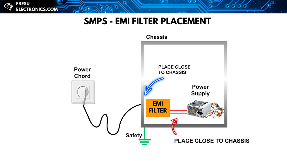
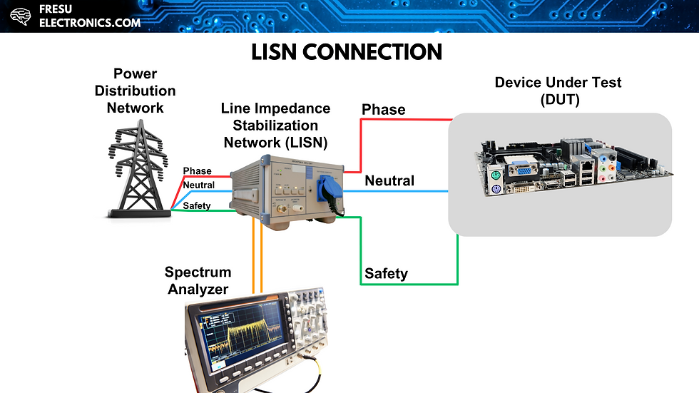
Positioned between the AC rectifier and the DC/DC converter, the input filter, often referred to as an EMI filter, targets conducted noise by filtering out high-frequency components that could otherwise reach the grid. To ascertain its effectiveness, engineers utilize a Line Impedance Stabilization Network (LISN) during testing. This tool standardizes impedance between the AC source and the converter, offering a consistent framework for noise measurement.
The LISN connects between the grid and the device under test. It channels noise currents through a defined path, allowing spectrum analyzers to quantify the resulting voltage. Measurements typically cover the frequency range of 150 kHz to 30 MHz, which aligns with common switching frequencies and their harmonics. Regulatory standards, such as those outlined in EN 55022 Class B, stipulate acceptable noise levels in dB microvolts. This rigorous testing process validates the performance of the EMI filter, which plays a crucial role in compliance certification.

Navigating Regulatory and Design Challenges
Adhering to EMC standards is an absolute requirement enforced by governmental bodies to prevent electromagnetic chaos. For switching converters, noise spikes caused by harmonics—multiples of the switching frequency—often intrude into regulated frequency bands, even if the fundamental frequency is below 150 kHz. This complexity escalates the design challenge, as engineers must customize input filters to mitigate harmonics without incurring excessive costs or size penalties.
The LISN’s standardized impedances, which include series inductors and measurement resistors, allow for precise noise characterization. Spectrum analyzers can sweep this range with a 9 kHz bandwidth, clarifying whether noise levels comply with regulatory limits. Meeting these requirements not only necessitates technical expertise but also strategic selection of components, especially as switching noise can become pronounced in high-power applications.
Strategies for Successful Input Filter Design
Select the Right Topology: Input filters can consist of various topologies, including passive RC, RL, or RLC configurations. Each has its advantages based on the specific converter application. For instance, an RLC filter can provide better attenuation at certain frequencies but may introduce additional complexity.
Component Quality Matters: Using high-quality components such as inductors with low DC resistance and capacitors with low equivalent series resistance (ESR) can enhance filter performance. This not only improves efficiency but also extends reliability under different operating conditions.
Simulate Early and Often: Before implementation, extensive simulations can highlight how the input filter interacts with the converter's existing circuits. Tools like SPICE can accurately model complex interactions, helping to strike a balance between filter effectiveness and performance stability.
Conduct Prototyping and Testing: After initial design and simulation, building a prototype is essential. This allows for real-world testing and adjustments based on observed performance. Using LISN during this phase provides insights into noise characteristics and compliance with regulations.
Iterate Based on Feedback: Documenting performance metrics and iterating designs based on testing results are vital. Continual refinement helps align the input filter with regulatory requirements and operational demands.
By implementing these strategies, engineers can create input filters that not only comply with EMC standards but also uphold the expected performance levels of switching converters.
Elevating Converter Design Through Input Filter Mastery
Mastering input filter design is crucial for electronic engineers working with switching power converters. It bridges the gap between regulatory compliance and operational efficiency, effectively addressing conducted EMI while preserving closed-loop performance. The combination of EMI filters and LISN testing equips designers with the necessary tools to meet stringent standards like EN 55022, ensuring their solutions are robust and market-ready.
By developing expertise in this essential area, engineers can deliver innovative power supplies that shine in efficiency, reliability, and electromagnetic harmony. These qualities are the hallmarks of state-of-the-art power electronics, making the mastery of input filter design a valuable asset in any engineer's toolkit.
.png)


Comments